Measuring system Siver Data can be used in the following cases:
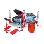
For measurements during the process of collision repair.
When it’s impossible to detect visually the condition of the car body and it needs an documental approval.
The measuring system provides noncontact multidimensional measuring by fixing pointer’s position and further 3D modeling. Siver Data incorporates the principle of binocular vision: like a human eye, when we need to determine distance to the object. Two cameras located at the ends of the measuring beam perform “eyes function”. As soon as contrast object (LED lights located in special order on the target) appears into the field of view of two cameras, the system accurately computes 3D coordinates.
SIVER DATA performs point-to-point measurements quickly and accurately. The system provides 1 mm accuracy of measurements.
The Siver Data measuring system has a Pattern Approval Certificate of Measuring Instruments which confirms the measurement accuracy and allows the measuring system users to submit the data on the car body condition both to customers and insurance companies.
Benefits of innovative Measuring system Siver Data:
- No mechanical parts, no complicated electronics, no lasers.
- Measuring beam can be located any way. Pointer is mechanically independent (not connected with rails). It gives more flexible and comfortable use.
- Not demands installation on the car (there are no targets, gauges, rulers)
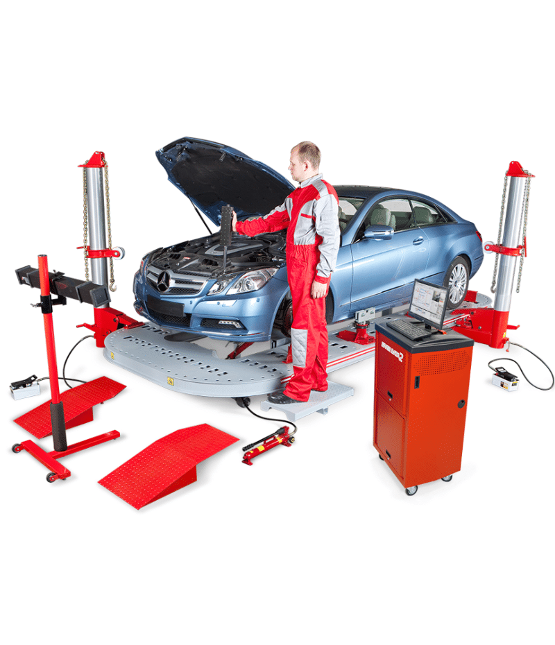
- Not fastened to a bench. It is possible to use the system on several benches with the minimum expenses of time for installation and carrying.
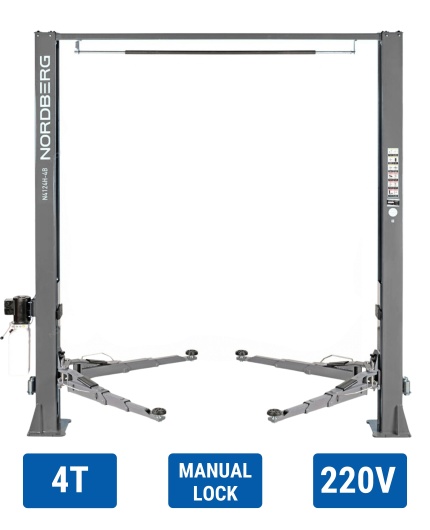
- Due to absence of requirements on system installation it’s not necessary to install the car on bench – it is possible to make fast express analysis and preliminary alignment of a body on regular 2-post lift.
- The measurements by the system do not demand any adapters. There is no risk to lose the adapter. No time required for changing adapters.
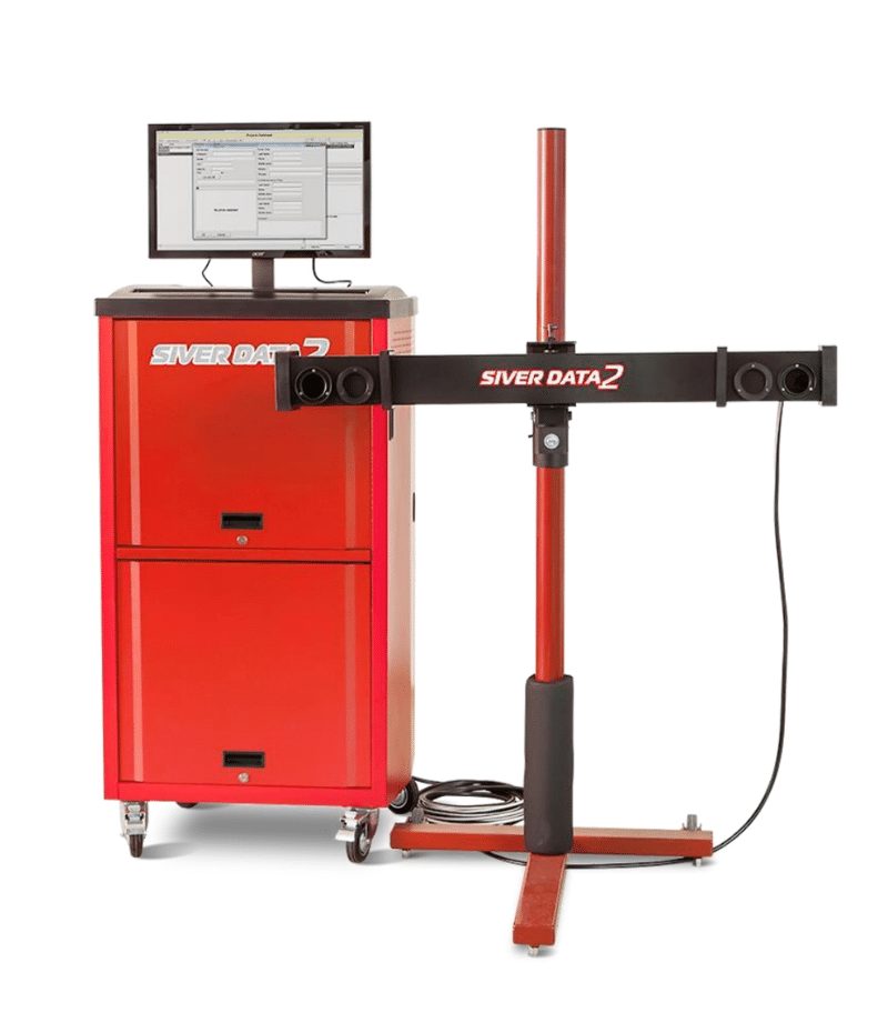

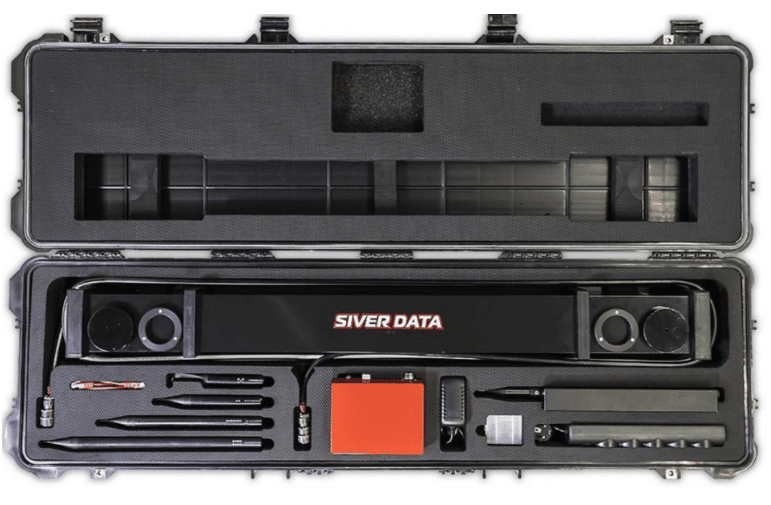
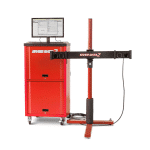
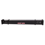
A measuring unit is a rigid metal beam incorporating two video cameras. The beam consists of two members: an outer protective casing and articulated precision rod with cameras. Such a structure reduces the risk of deformation of critical assemblies and enhances the operational robustness.
Pointer contents 23 LED lights. Pointer works from built in AA batteries.
Control commands are communicated to the computer optically via a wireless link.
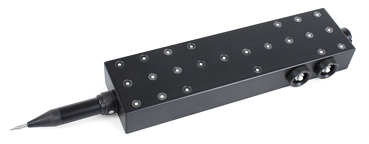
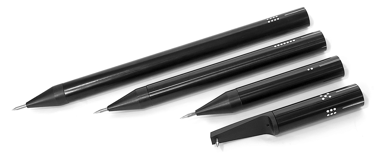
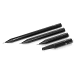
The system comes complete with several replaceable probes:
1. Basic (regular) probe: the shortest non-removable probe ensuring the highest measurement accuracy.
2. Side rotary probe: can turn around the centerline and fix in four positions. Used to either measure the points on the vertical surface or to facilitate the vertical orientation of the pointer in case of insufficient space between the bottom and the pulling system deck.
3. Long probe: used in cases when a measured point hides behind a car bottom projection which obstructs the camera’s view and obscures the pointer.
4. Extra long probe: ideal for accessing deep points.
Switching between probes is possible in the course of measurements. The probe number is communicated to the computer remotely. For data transfer, just press a special button on the pointer.
A switching unit incorporates a power supply unit for the measuring unit and an interface board to communicate with the computer.
All equipment has the Certificate of Conformity to Safety Requirements (РОСС RU.MT20.B10732) and Pattern Approval Certificate of Measuring Instruments.
Working order
1. Starting a new project
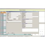
- Choose a model of the vehicle and enter owner’s information.
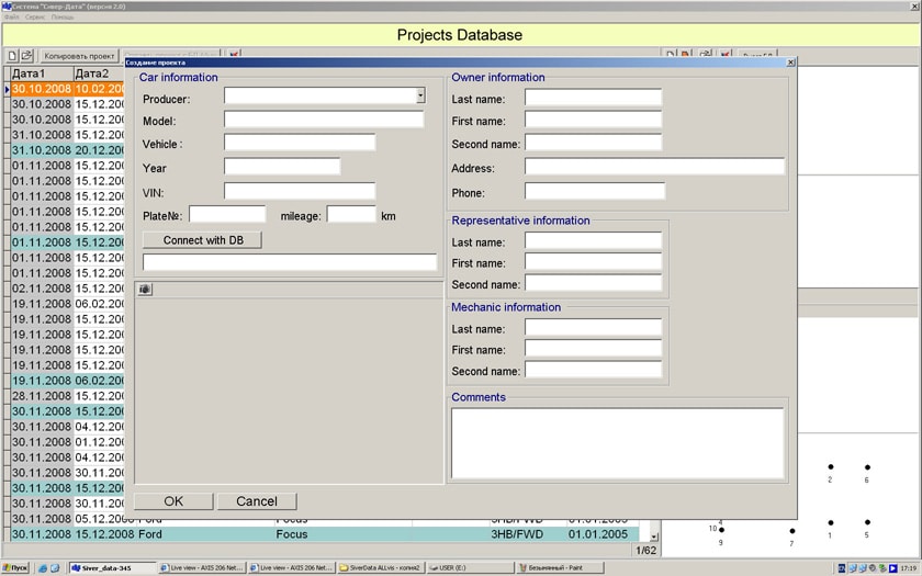
2. Primary inspection
- Inspect the vehicle to make a deduction which sections are damaged.
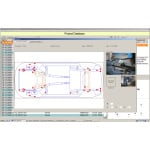
- Then open specifications database.
- Choose on the picture reference points in undamaged section (preferably 3-6 ).
- Choose points in undamaged section (e.g. longeron, suspension attachment points etc.).
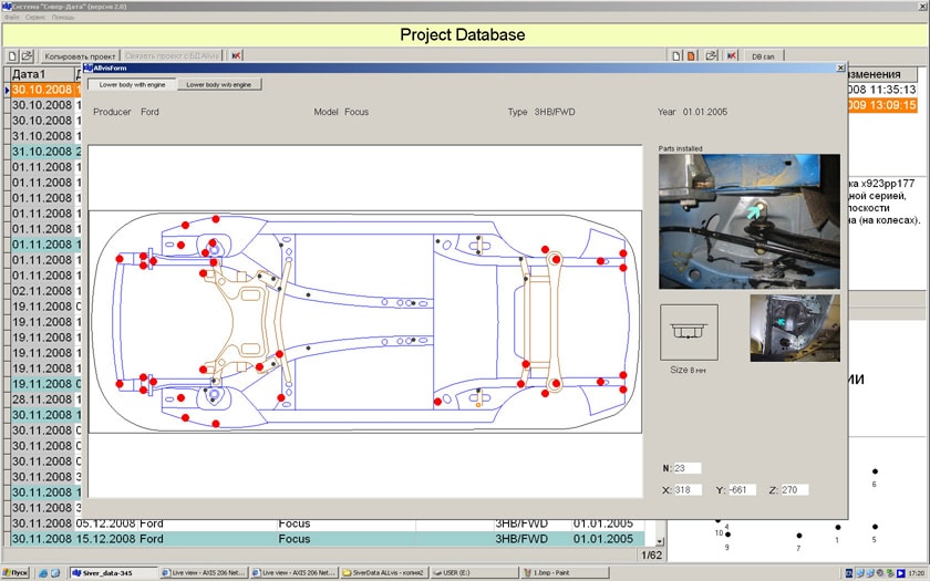
3. Measuring procedure
- In accordance with the instructions of the program, measure all the chosen reference points in the most convenient sequence. After cameras capture position of the LED lights, system analysis and identifies multidimensional coordinates of the pointer and consequently coordinates of the probe’s end. Thus, to measure misalignment required just to put the probe to control points of the car body. LED lights must face to cameras.

4. Analysis of measurement results
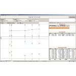
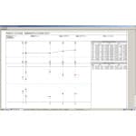
- The system automatically combines all measured points with reference points in database, using successive approximation method. Misalignment points with a difference from the specifications 5 mm appear Red. Points with a deviation from the specifications less then 5 mm appear Green.
Measurement results can be printed.
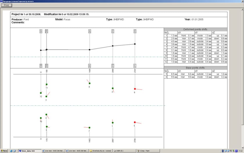
Mobile System Kit:
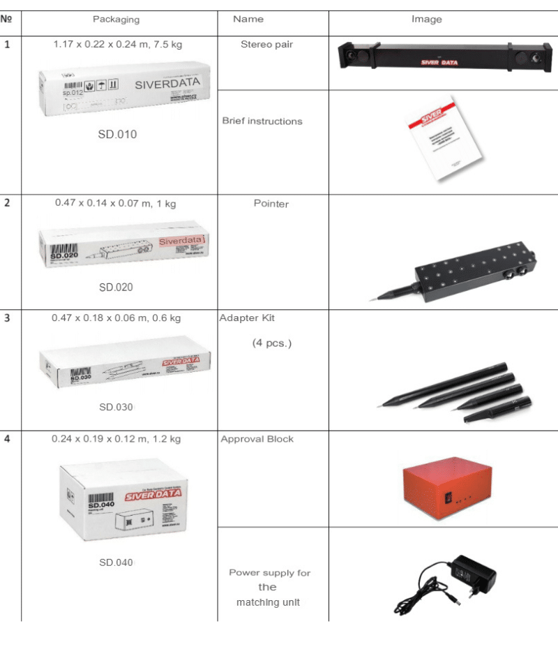
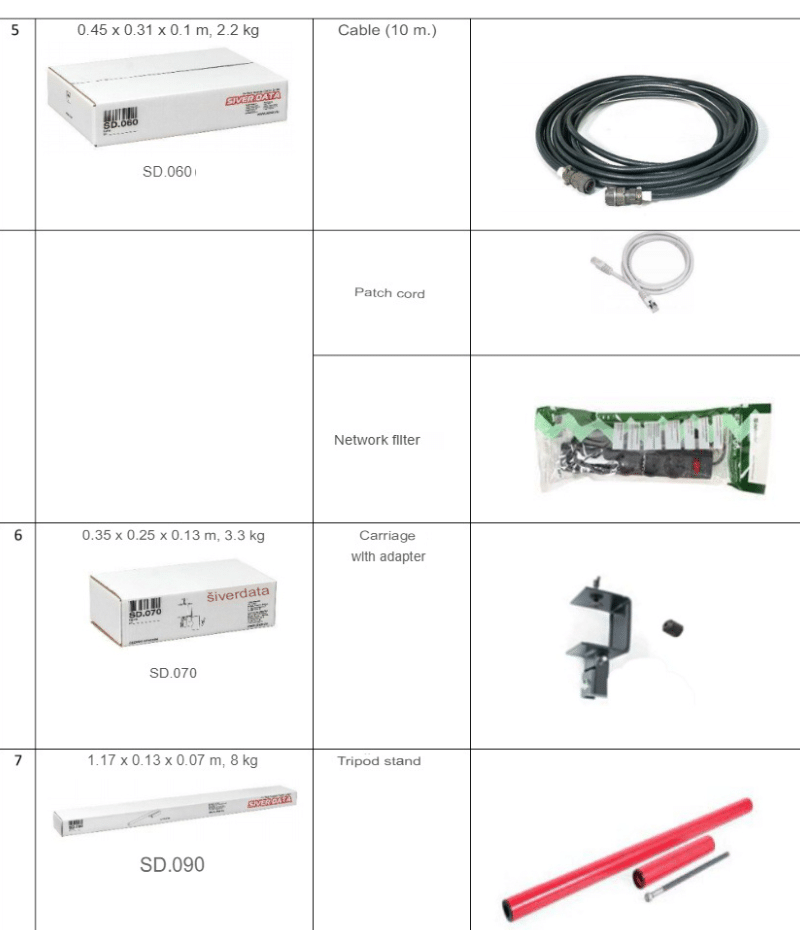

With the Siver Date, you will be able to measure the position of any points of the body. To get started, you need to install a tripod with the system and pick up a wireless pointer. The system is very compact, mobile and easy to use. It will save you a lot of time and effort!
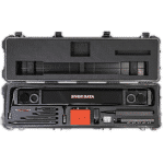
The elements of the system are well packed in individual boxes. All boxes are placed in a cardboard module on a pallet.
All the elements of the system are placed in the case for the Siver Date. It can be used both for storing the system in the service and for working "on the go".




Reviews
Clear filtersThere are no reviews yet.